Mechanical redesign for a 200× heavier ball · Dec 2025
Redesigned a ball balancing platform for a 200× heavier ball: a topology-optimized plate, stronger links and a ball-joint-free manipulator.
Redesigned the platform around a 538 g steel ball so a force-torque sensor could find it
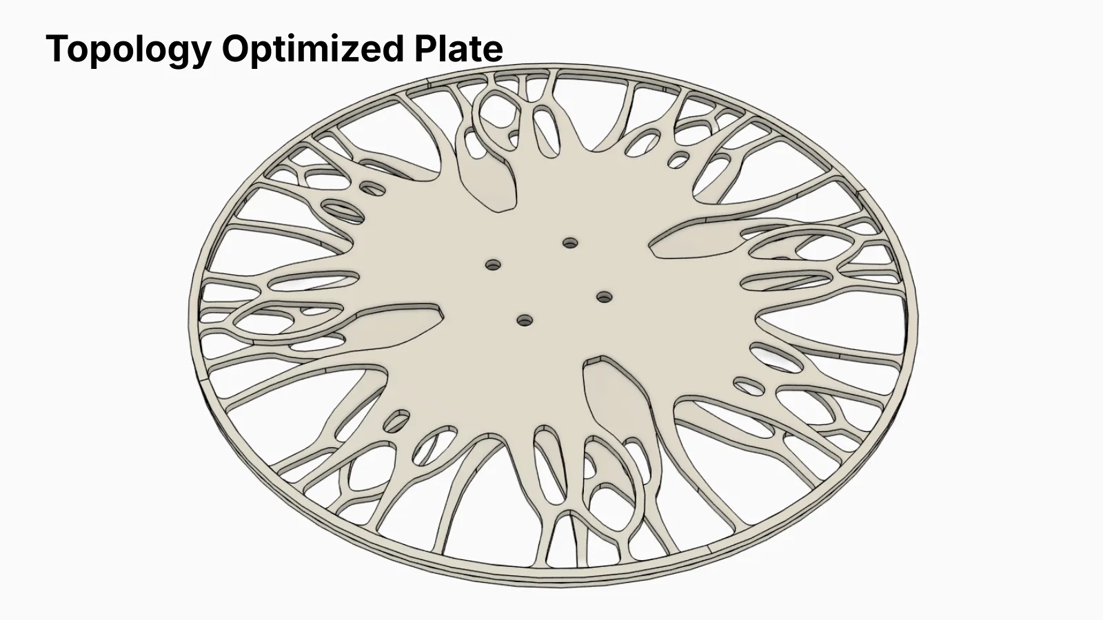
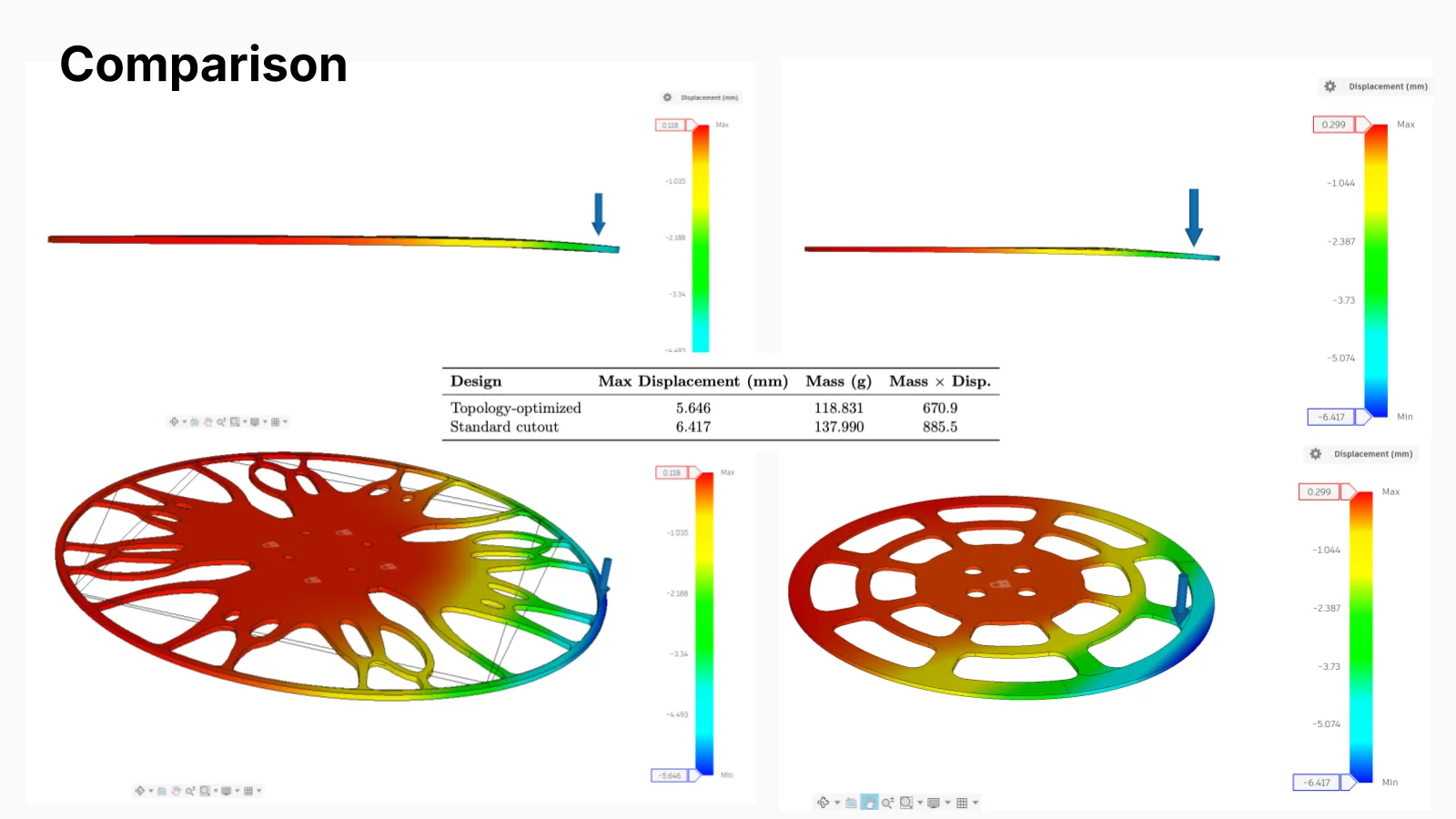
Topology-optimized the plate: 14% lighter and 12% stiffer than a standard cutout design
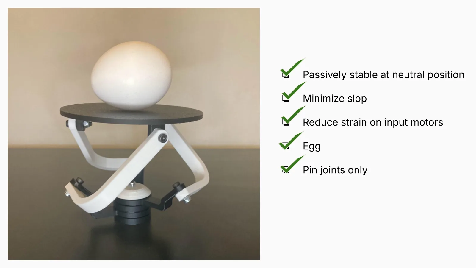
Designed a ball-joint-free spherical parallel manipulator with pin joints only
A 3RRS ball balancing platform, rebuilt so a force-torque sensor under the plate could find the ball by feel. That meant a 538 g steel ball, 200 times heavier than the ping-pong ball it replaced, and I led the mechanical redesign it forced: the plate, the linkages and joints, and a new ball-joint-free mechanism.
The twist
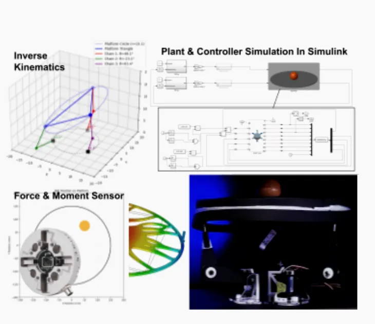
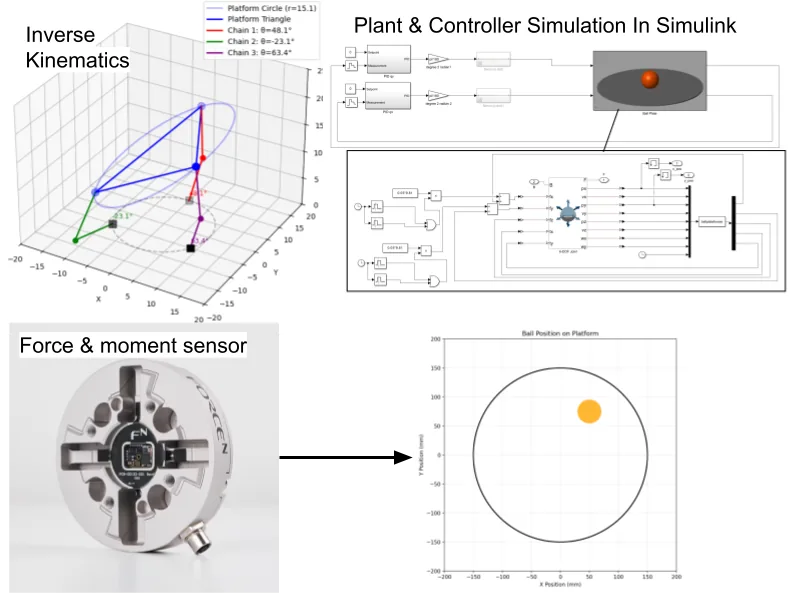
The course platform balances a 2.7 g ping-pong ball under an overhead camera. Our team of five set out to find the ball by feel instead: a ForceN 3-axis force-torque sensor under the plate reads the normal force and the two tipping moments, and the ball's position follows from them. A ping-pong ball barely registers on a load cell, so we switched to a 538 g, 2-inch 440C steel ball, 200 times heavier. That one change broke almost every part of the platform, and redesigning the mechanics around it was my main job.
A plate that is stiff and light
Any flex in the plate corrupts the moments the sensor reads, yet every gram it adds loads the links and servos. My first plate, three 3 mm laser-cut acrylic discs bonded with UV resin, was stiff enough but heavy enough to break the links. A single 3 mm plate was light, but with the ball near the edge it sagged onto the base and the readings became useless. For the third iteration I ran a topology optimization against the ball-at-the-edge load case and compared it in FEA with a conventional pattern of concentric cutouts:
Topology-optimized: 118.8 g, 5.65 mm maximum deflection
Standard cutouts: 138.0 g, 6.42 mm maximum deflection
The topology-optimized plate was 14% lighter and 12% stiffer, so it went into the build. Every geometry was laser-cut in paper first to check the fit before committing to acrylic.
When the links cracked
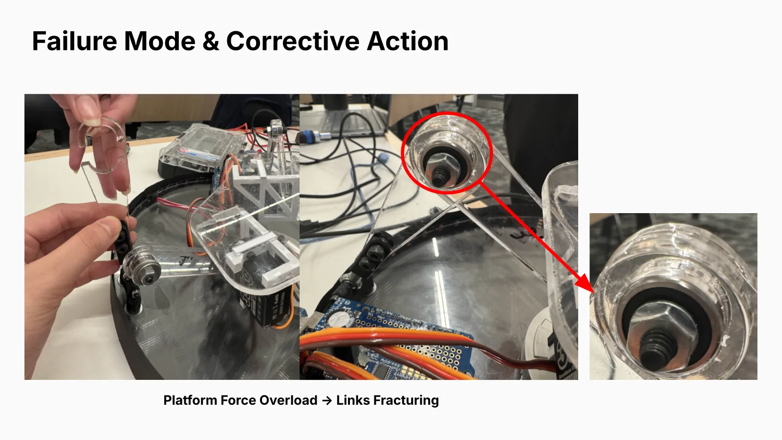
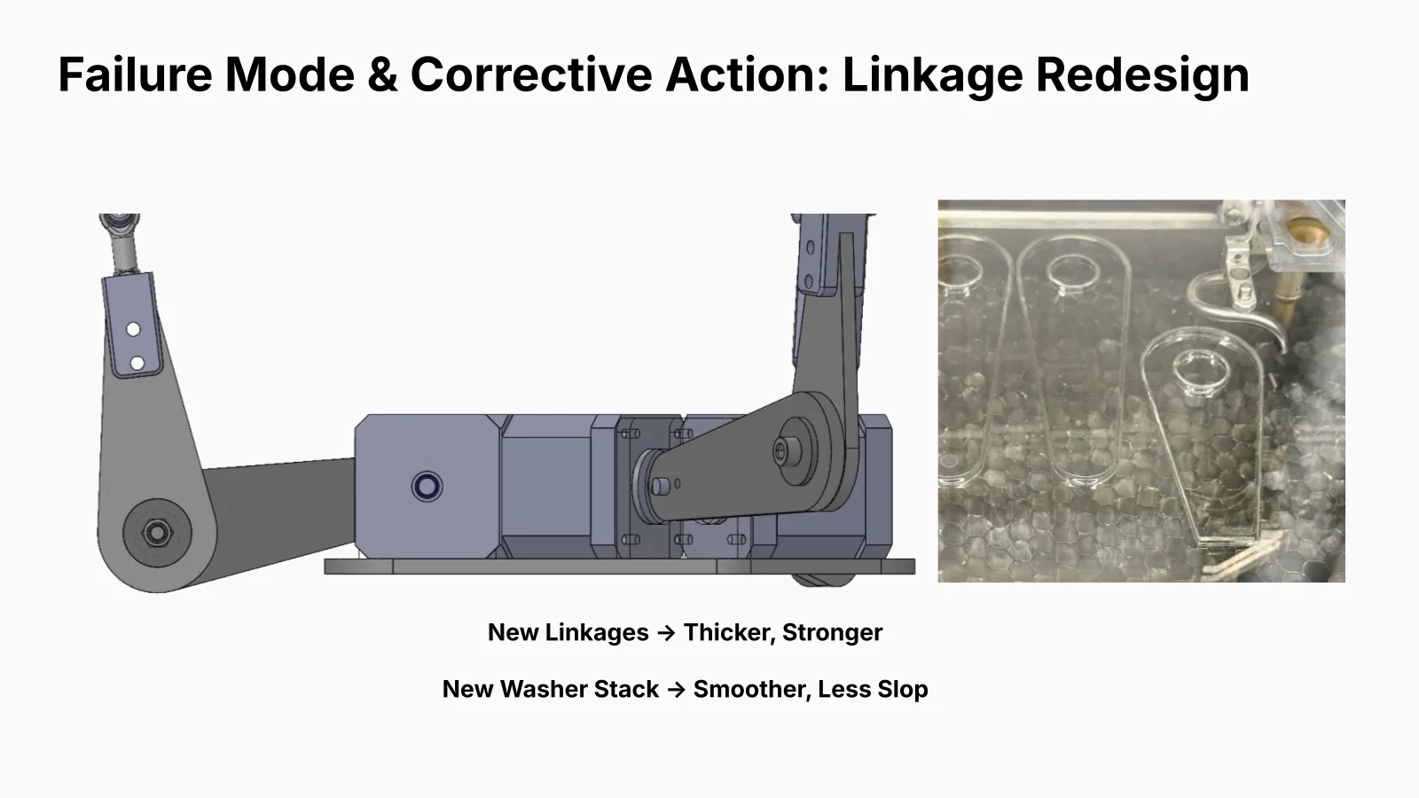
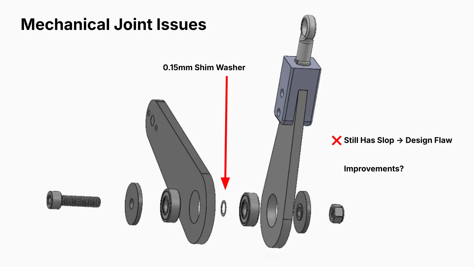
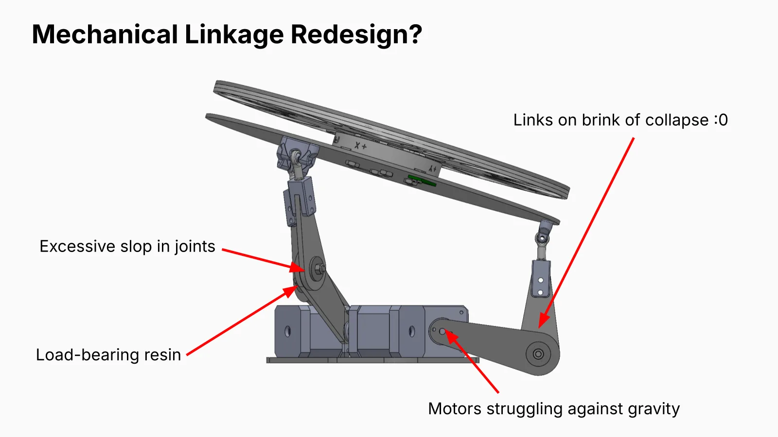
With the first plate, the links cracked at the joint between link 1 and link 2. As the servos tilted the plate, the heavy ball resisted and pushed a large lateral force down the linkage chain; the link most perpendicular to the tilt took it as shear at the thinnest acrylic around the bearing. I redesigned the links wider around the bearings for shear capacity, added printed end stops so link 2 couldn't peel away from link 1, and rebuilt the joint stack with thin shims, tuning their count by trial until the slop was minimal without binding. It helped, but some play remained: acrylic links on ball joints were the limit, not the tolerances.
Servos that fought back
The stock MG995 servos stalled outright. 35 kg brushless servos had the torque and almost matched the ping-pong ball's performance, but drew 20 A spikes that no bench supply on campus could deliver. Higher-geared Studica smart servos could lift the load, but on a fast downward tilt the ball drove the plate faster than the servos would follow, back-driving them into generators that tripped the supply. The fix was a protection circuit between the servo shield and the supply: a 15 A Schottky diode to block reverse current, and a 4,700 µF capacitor with a 10 Ω, 100 W dump resistor to absorb and burn off the returned energy.
Getting rid of the ball joints
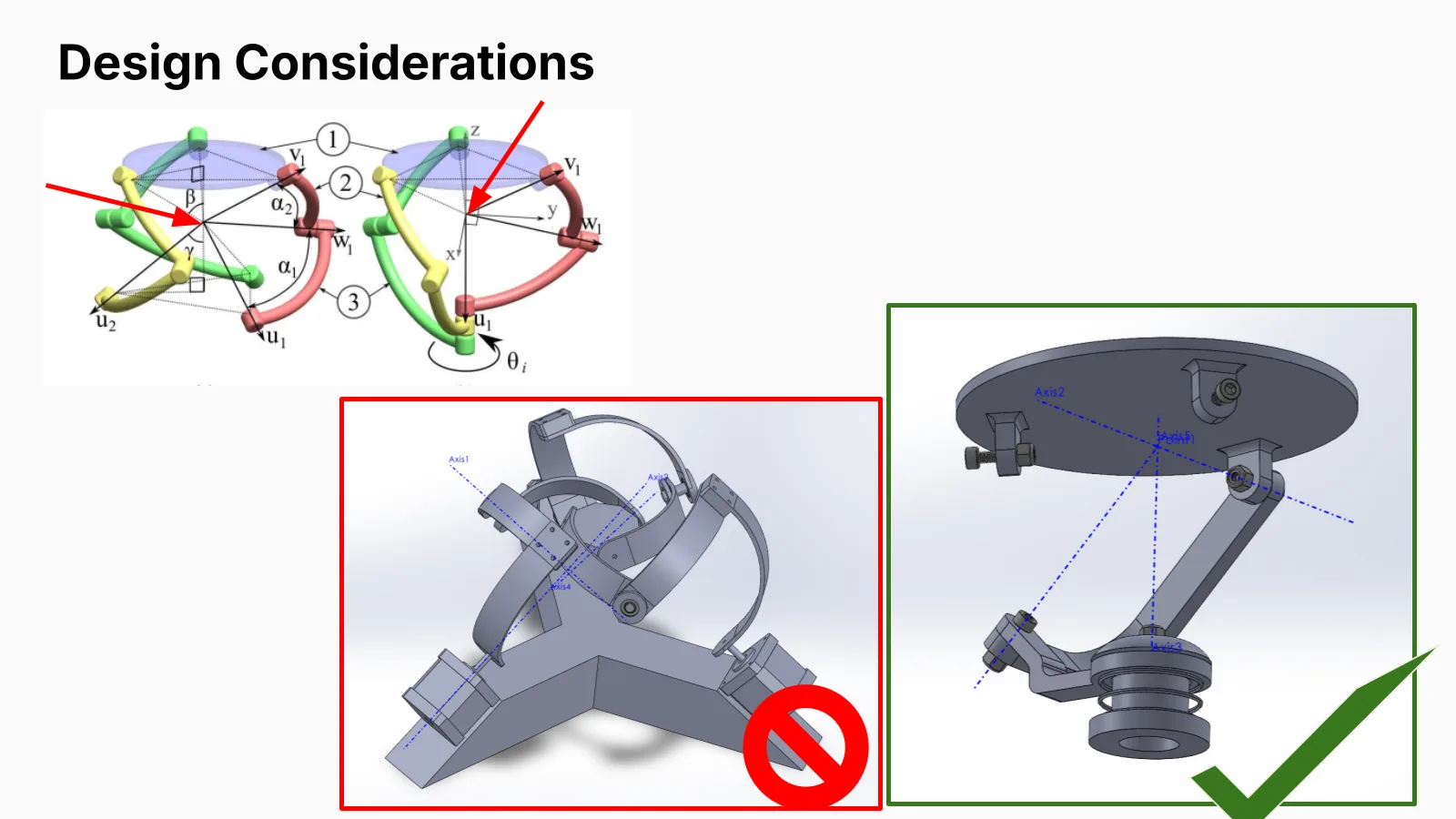
The slop pointed at a deeper fix, which became our second design question: remove the ball joints altogether. Of six concepts, including cable pulleys, magnetic levitation, two gimbal layouts and slotted links, I took a spherical parallel manipulator forward. It uses pin joints only, with every joint axis passing through one point, so the plate pivots about a fixed centre.
A first concentric-sphere design made aligning the axes and assembling the curved links impractical. The second uses coaxial inputs, base links angled 45° toward the centre axis and three identical L-shaped links, with lengths set so that every axis meets at the same point. Get that slightly wrong and the mechanism either won't assemble or locks to a single degree of freedom. The 3D-printed prototype holds its load at neutral with the motors off, moves smoothly with no bearings at all, and balances an egg.
Sensing and control
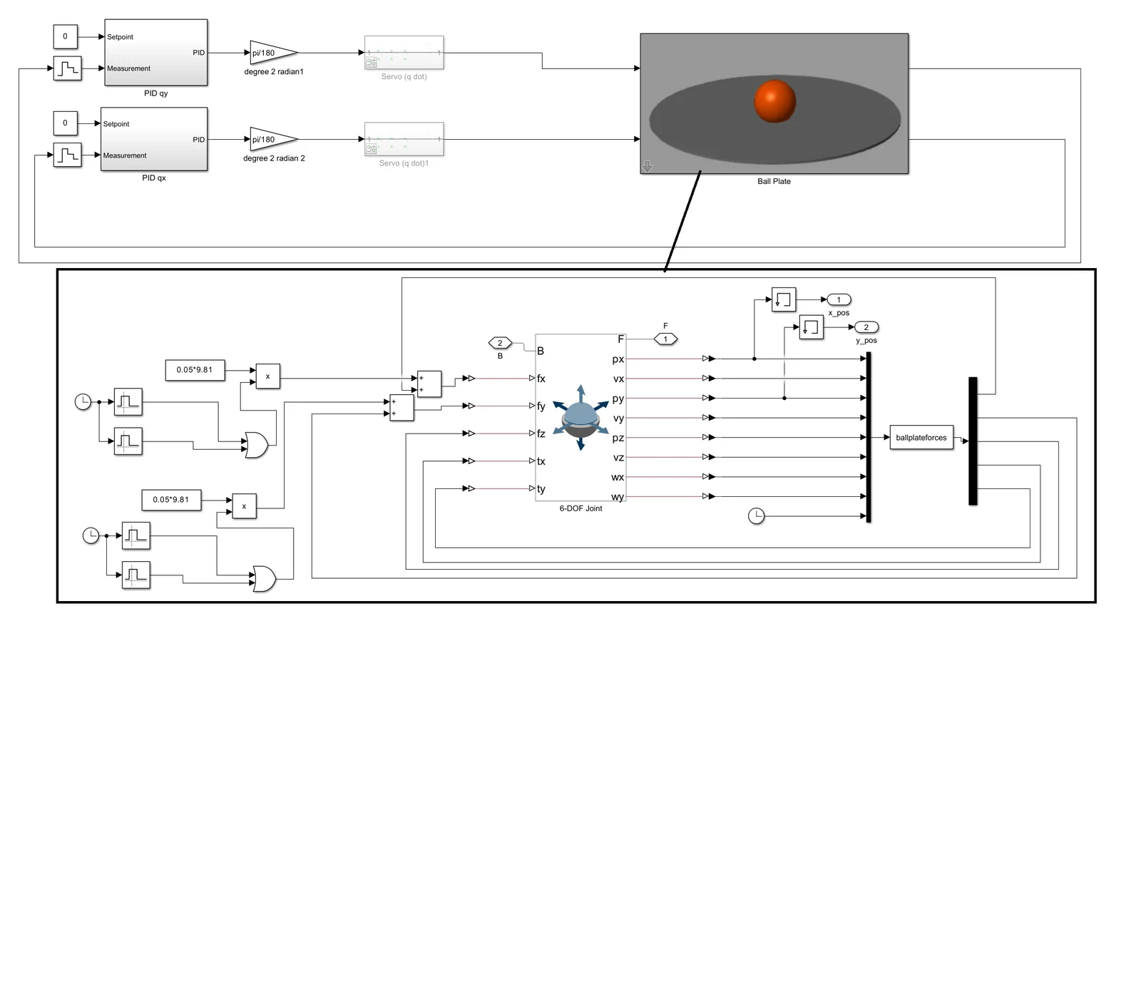
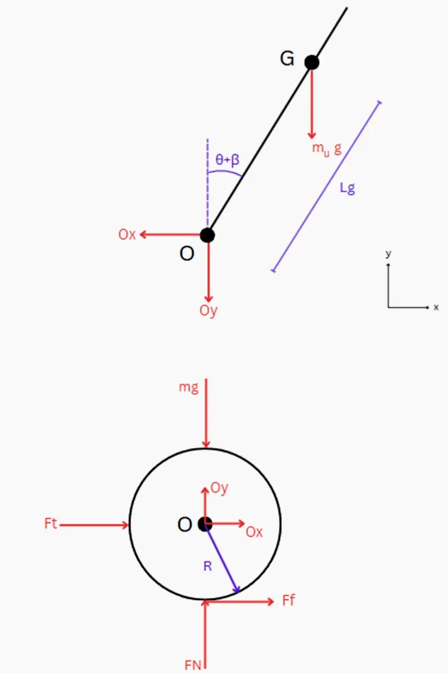
As a team, we estimate the ball's position from a quasi-static model of the sensor's force and moments, filtered and aligned to the plate, and benchmark it against an OpenCV Hough-circle tracker reworked for the mirror-like steel ball. Control is decoupled X–Y PID with velocity feedforward and extra derivative action to catch the heavy ball's momentum; trajectory planning was compared on a Simulink plant model.
SolidWorks
Topology optimization · FEA
Laser cutting · 3D printing
Kinematics
Python
Simulink
PID · feedforward
Media
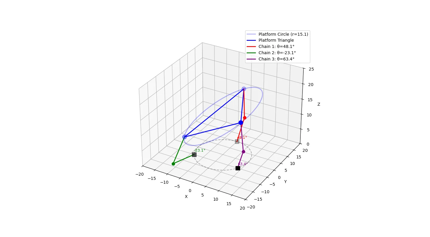
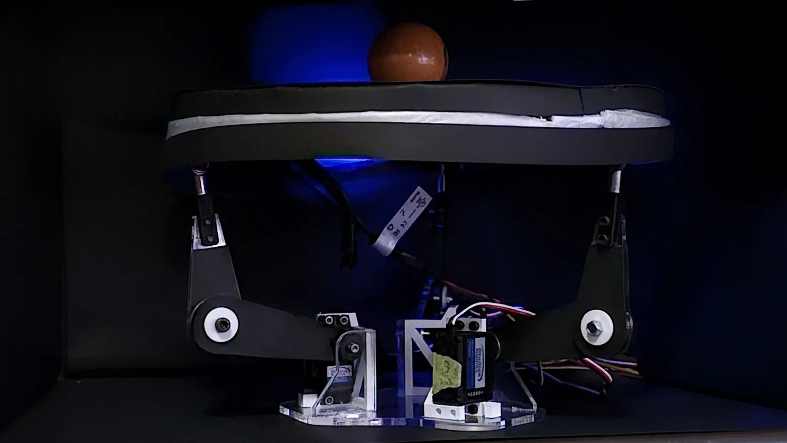
Assembly timelapseDesk setup with live ball-position and kinematics plotsPrototype tilting alongside the live 3D inverse-kinematics plotForce-torque sensor estimating contact positionFull system demo: the ball held on the plate; the LED ring turns green once balancedSimscape ball-on-plate simulationTrajectory planner profiles (simulation study)SolidWorks kinematic skeletonThe topology-optimized plateFEA: topology-optimized against standard cutouts, with the ball at the edgeThe first plate overloaded the links, which cracked at the bearingRedesigned links: wider around the bearings, with a new washer stackJoint stack: shims reduced the slop but could not remove itWhy the linkage needed a deeper redesignSpherical parallel manipulator layouts: every joint axis must meet at one pointThe 3D-printed spherical parallel manipulator, pin joints only, balancing an eggMatplotlib inverse-kinematics model of the three chainsSimulink plant and controller modelBall free-body diagram and overviewPrototypeKinematics, Simulink and sensor collage▶Inverse kinematics demo of the 3RRS manipulator▶Simscape ball-on-plate plant and controller simulation▶Ball position sensing using the force + torque sensor▶Trajectory planning▶Ball position sensing using the 3-DOF ForceN force/torque sensor (long form)Overview: inverse kinematics, the Simulink plant and controller, and the force/torque sensor